So, last time, you might recall that I had learned that I needed to clean the chassis grease out of the steering box, as it requires 600 weight oil, not grease. I did some research into this to find out why. Here's a pretty good synopsis of all the how's and why's, but here it is in a nutshell - It turns out, that up until sometime in 1931, the gear teeth were "square cut" (as opposed to "helical cut"), and so there is a possibility of the teeth pushing the grease out of the way and leaving a bare-metal contact area. Of course, this is no good, so oil was used, as it will run back in to the cavities.
This is good news! This means that a little bit of grease in the box won't hurt anything, and so I don't need to get it completely clean - just "clean enough." With that in mind, it was time to start cleanin'!
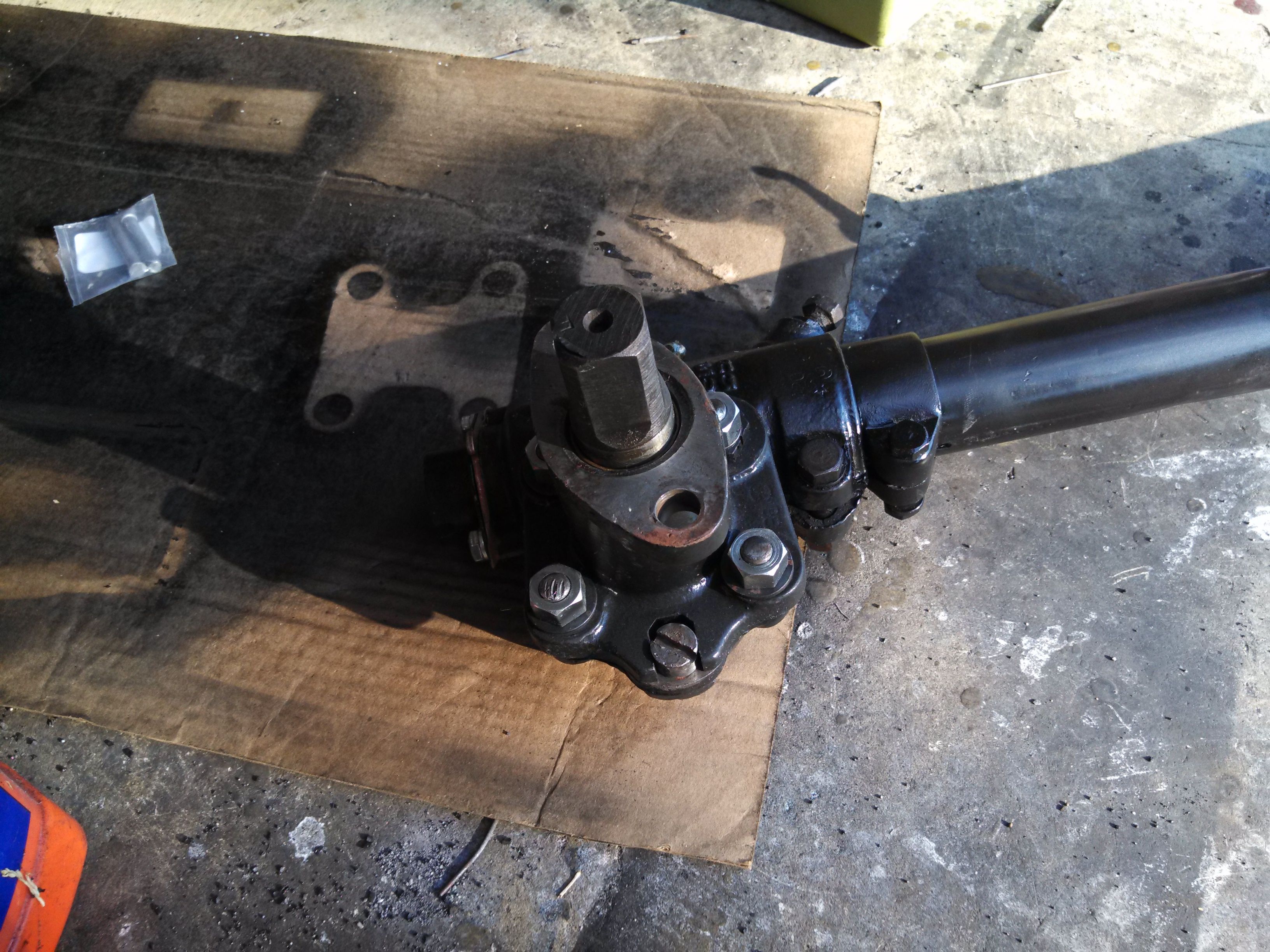
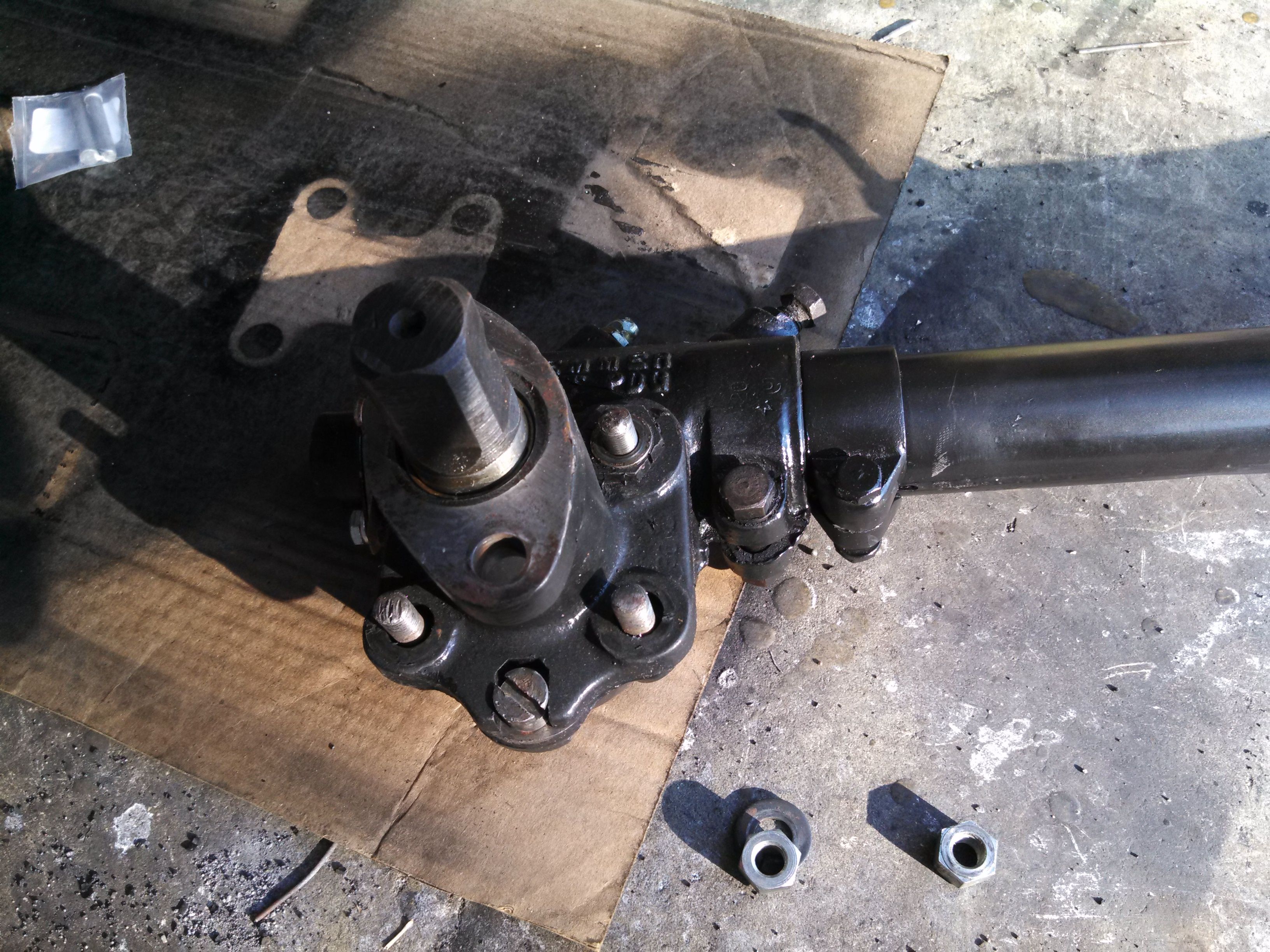
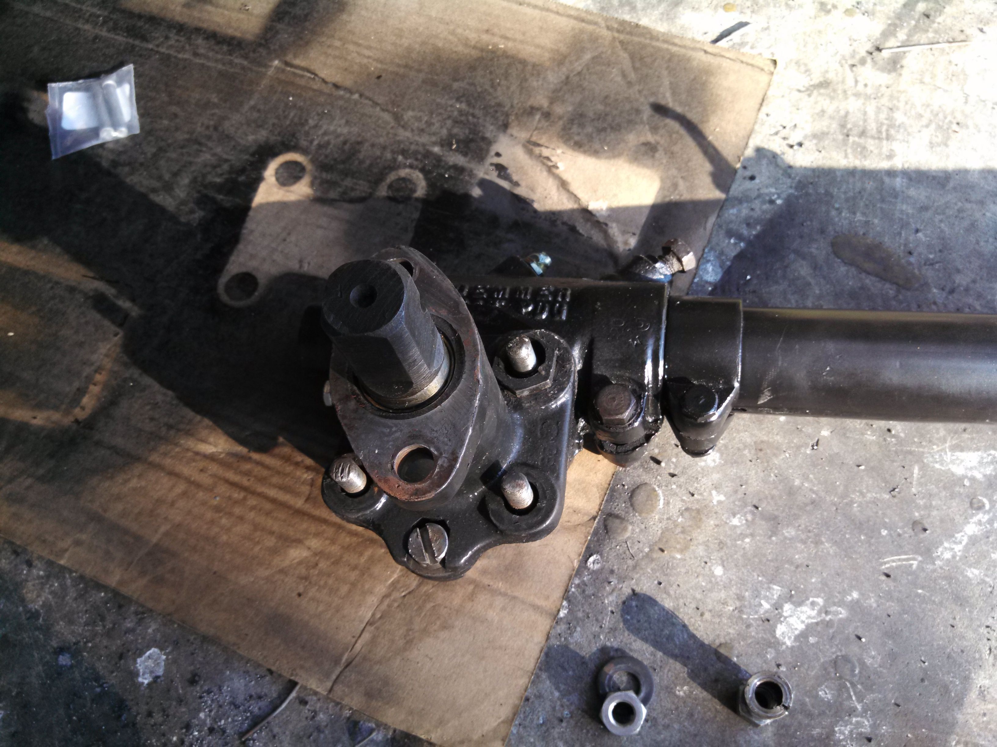
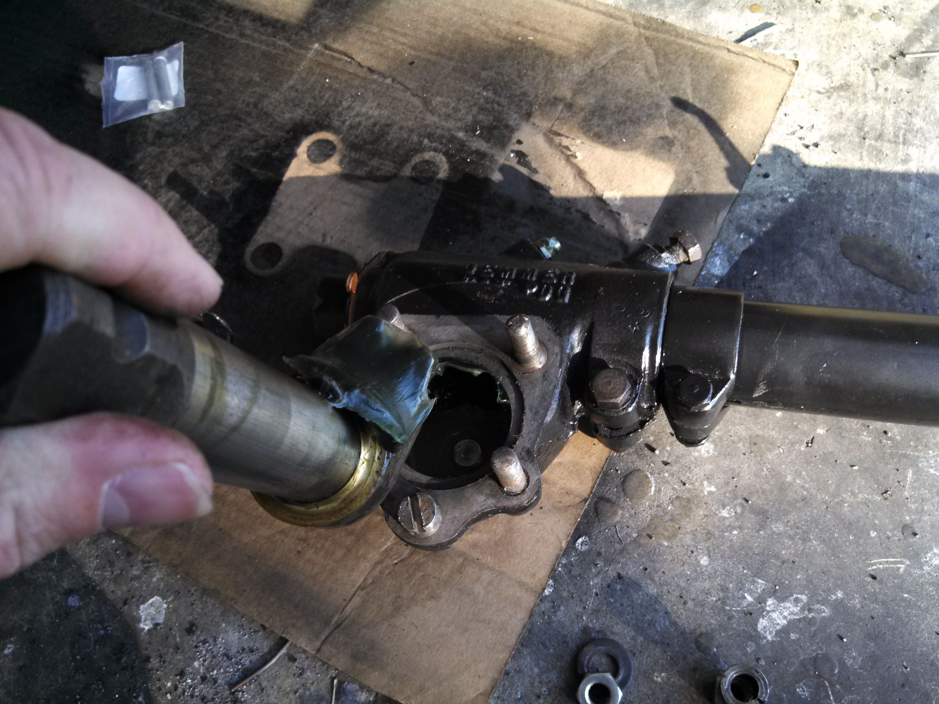
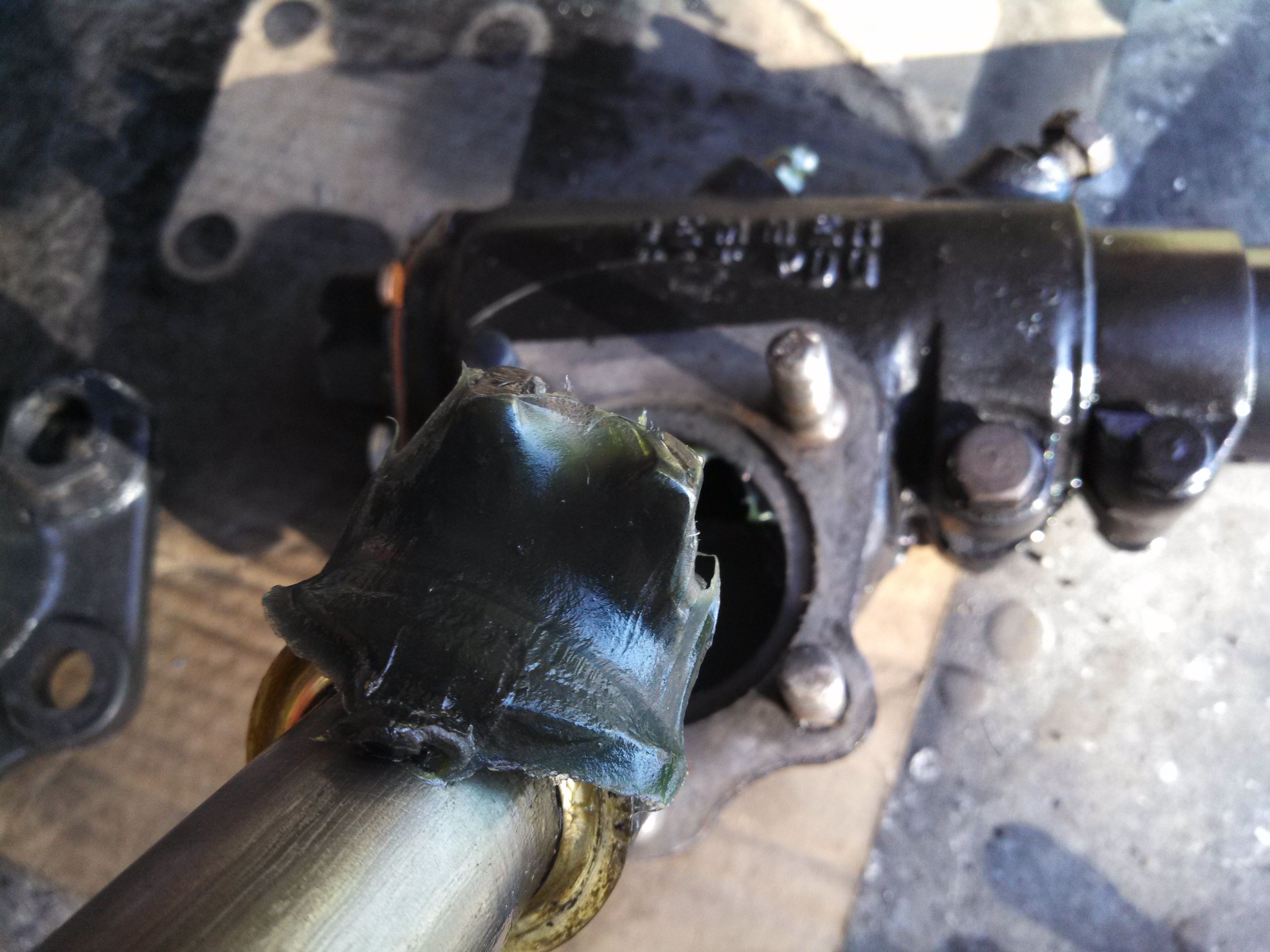
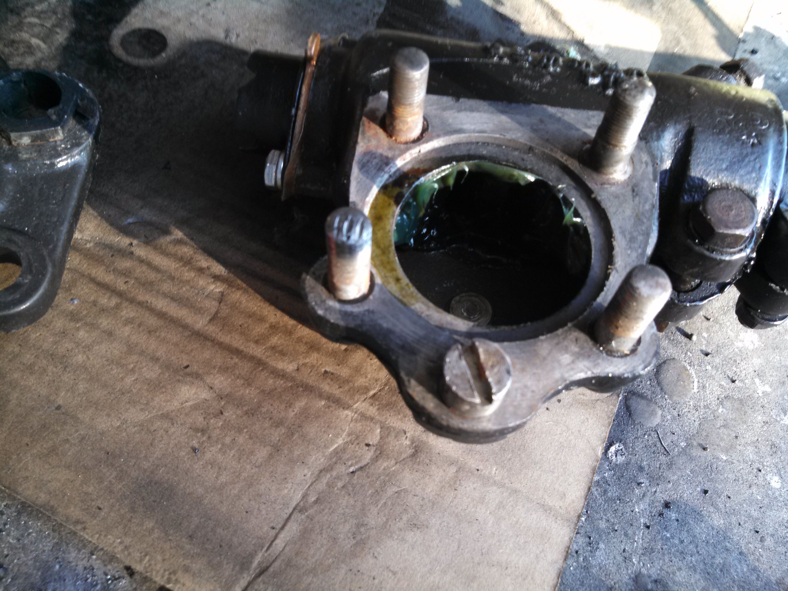
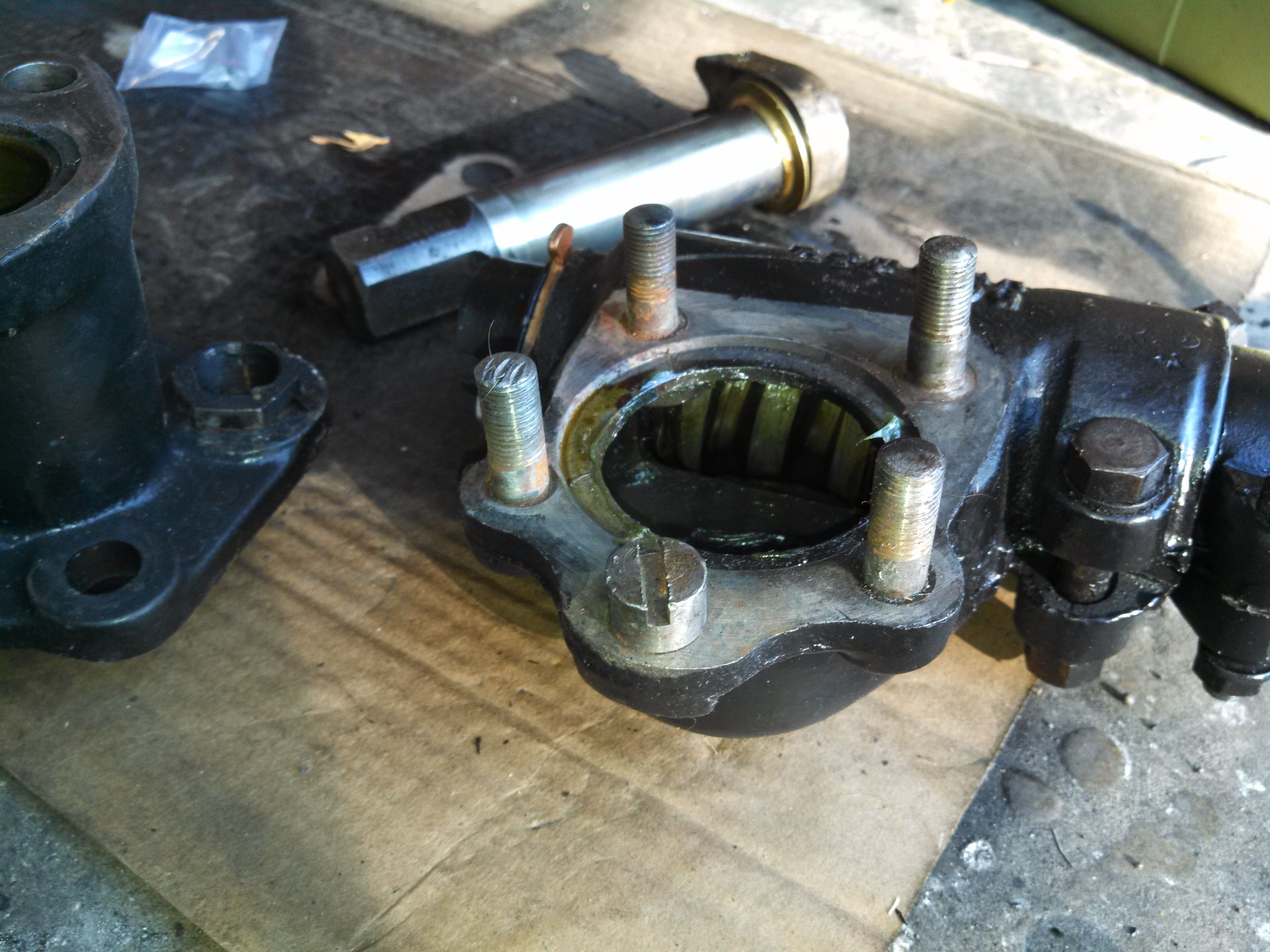
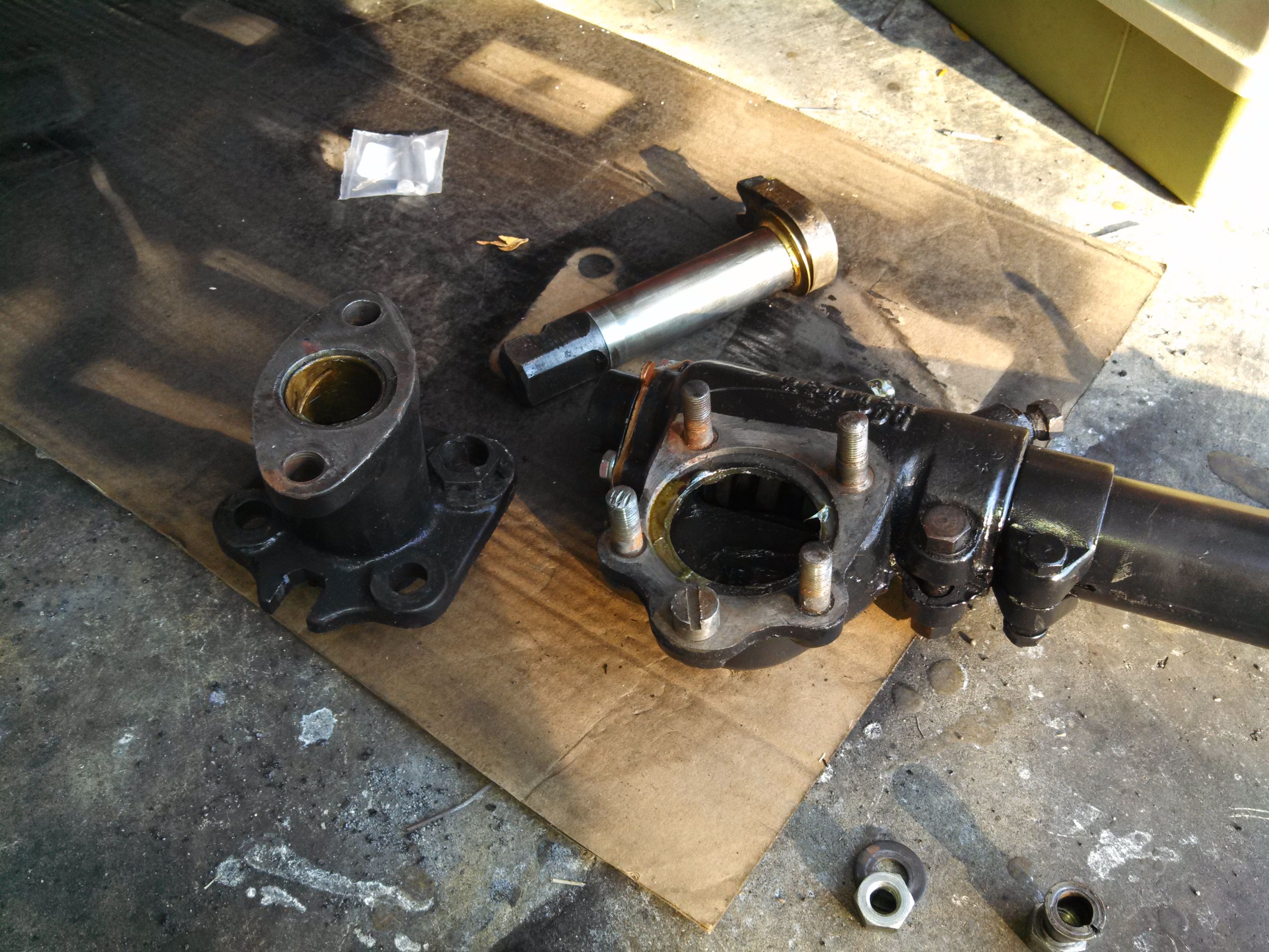
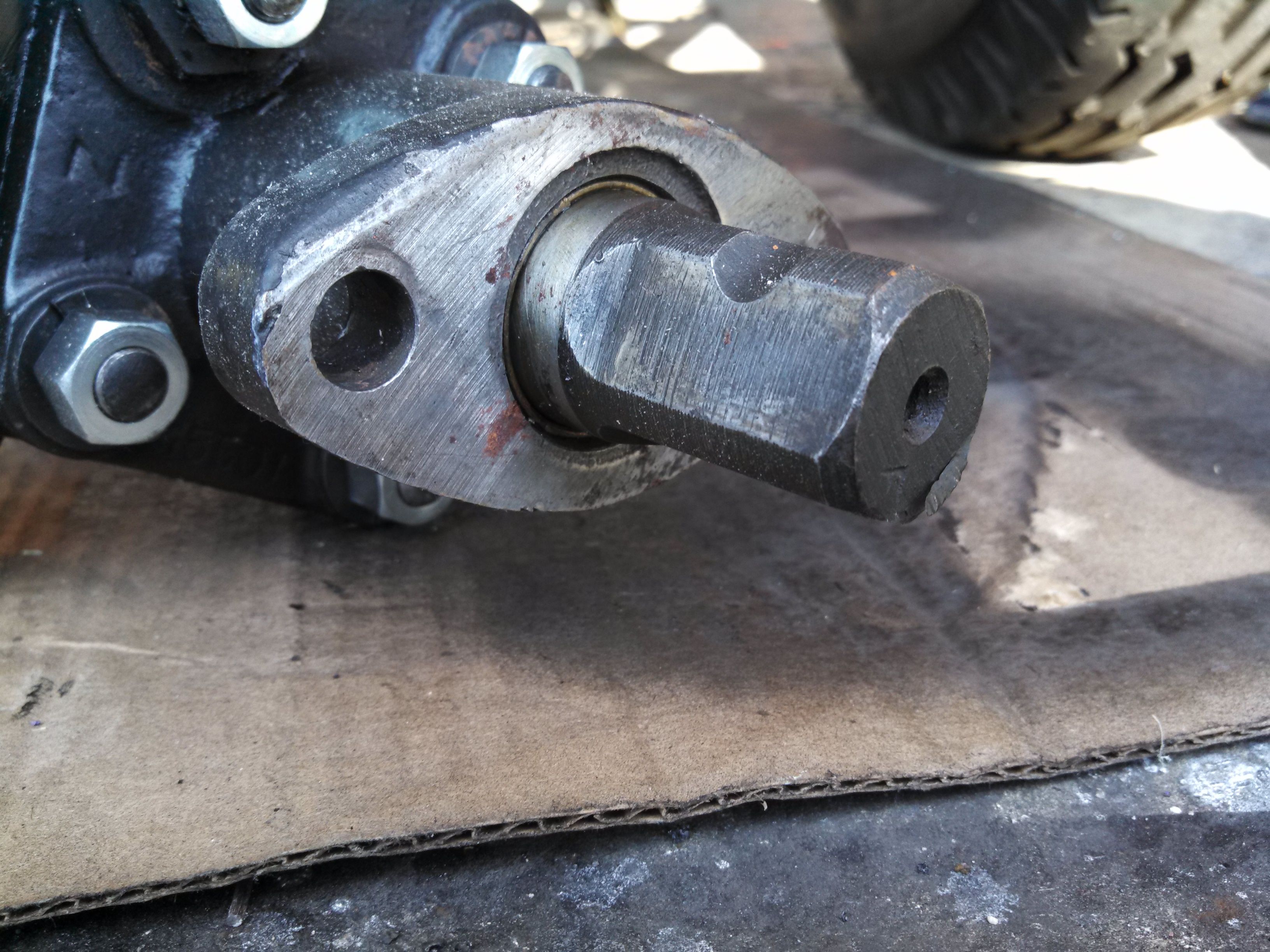
I did like last time, and tore down the box (but not the whole column) - This entailed leaving the steering column attached, but removing the parts of the sector housing, which is detailed in the pictures below:
You can see from the above pics that I didn't manage to get all that much grease into the housing before I ran out, and that's a good thing. Makes the clean-up a lot easier, I'd guess.
At this point, I just wiped off the sector and then stuck my finger in the box to dig out the grease like a big booger. Once I got as much out as I could, I had my daughter turn the steering shaft while I ran a gag along the worm gear. My sound engineering judgement *rolls eyes* tells me this is probably "good enough."
I put it all back together, and will spend some agonizing time some other day getting it all "tuned up.:
This got me to thinking about there being a heavy-weight oil in there, and how badly it might leak. That is, "How much oil's gonna leak from around the sector?" I did some more reading up (same link as above), and the answer is that if everything is clean and "tight," then leaking should be minimal.
But what's tight? Well, it would seem that "tight" is no more than about 0.5 to 1.0 mils clearance between the sector shaft and the bushings. Hell, I have NO idea what the clearance is in there, as I didn't replace any of it (because it looked like it was in pretty good shape). So, being an engineer (albeit an electrical engineer), I decided to drop in a rubber gasket at the interface between the mounting face and the frame. I took a bunch of measurements, and came up with something like this:
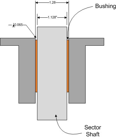
With those measurements in hand, I went to McMaster Carr, and chose an O-ring. We'll see if they work.
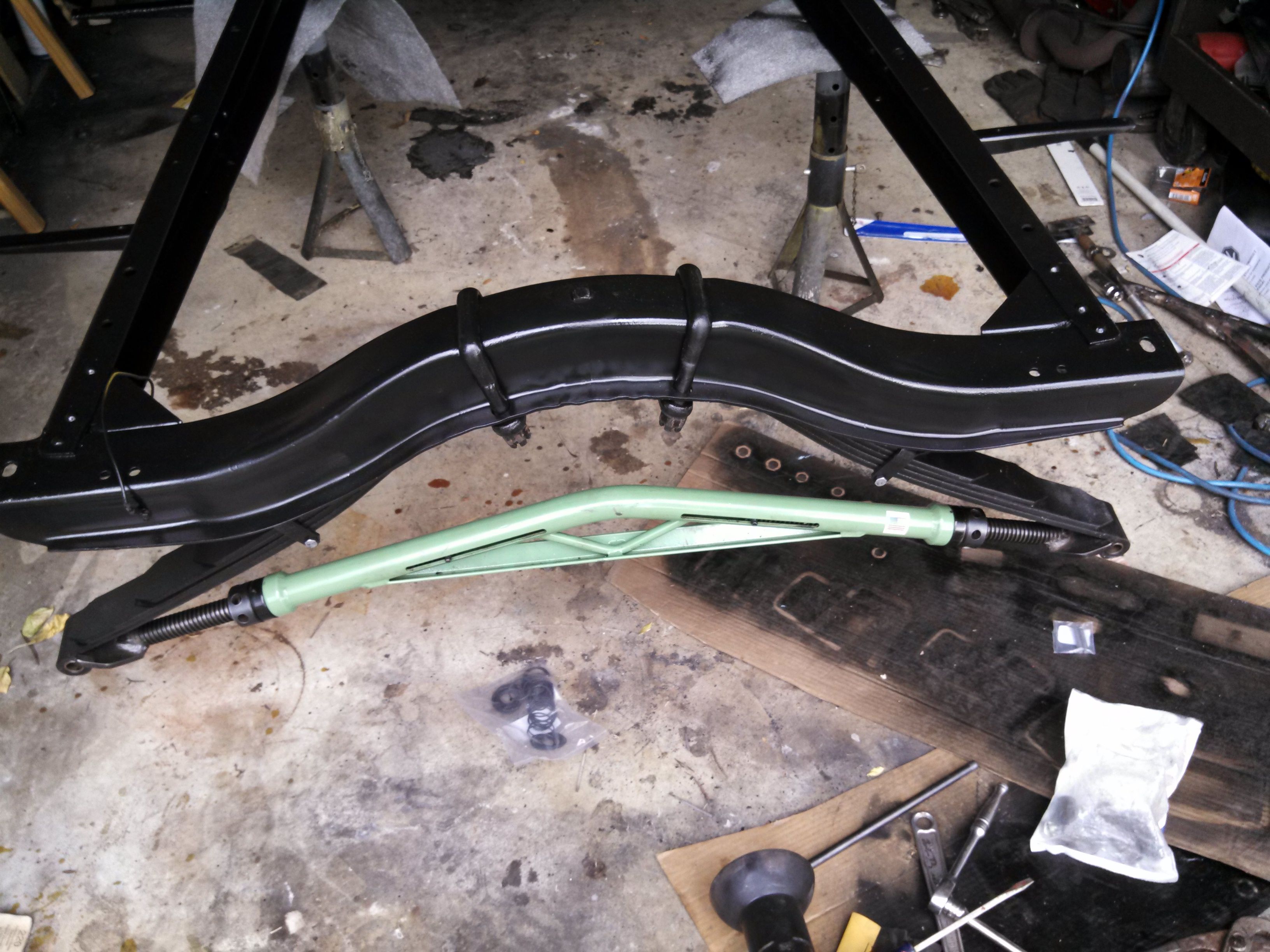
Last Month, I described the attempt to install the rear leaf, and the associated "Benny Hill music" that was playing in the background... I borrowed a "proper" spring spreader from the local Model A club, and my youngest daughter and I got the thing installed.
The spreader is a nifty thing, of a slightly different design than the one I built. It uses 7/8" all thread, has a couple of thrust bearings, and has a bungee cord inside it to keep the ends from falling out. The tool guy at the club said somebody else had used it and said it was so easy to turn out with those thrust bearings that they were able to move their springs most of the way out by hand...
I'll tell you what - it's much easier to turn than the one I built. Now I'm not wanting to call someone out as being full of the stinky stuff, but I'm thinking that either they had weak springs, of forearms like a gorilla...
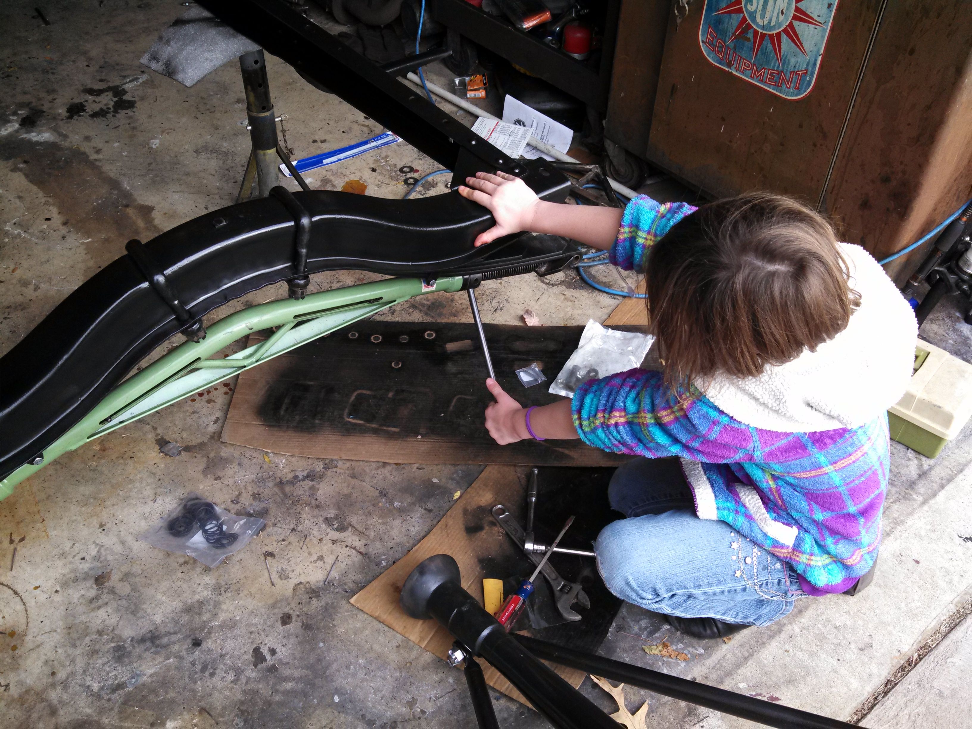
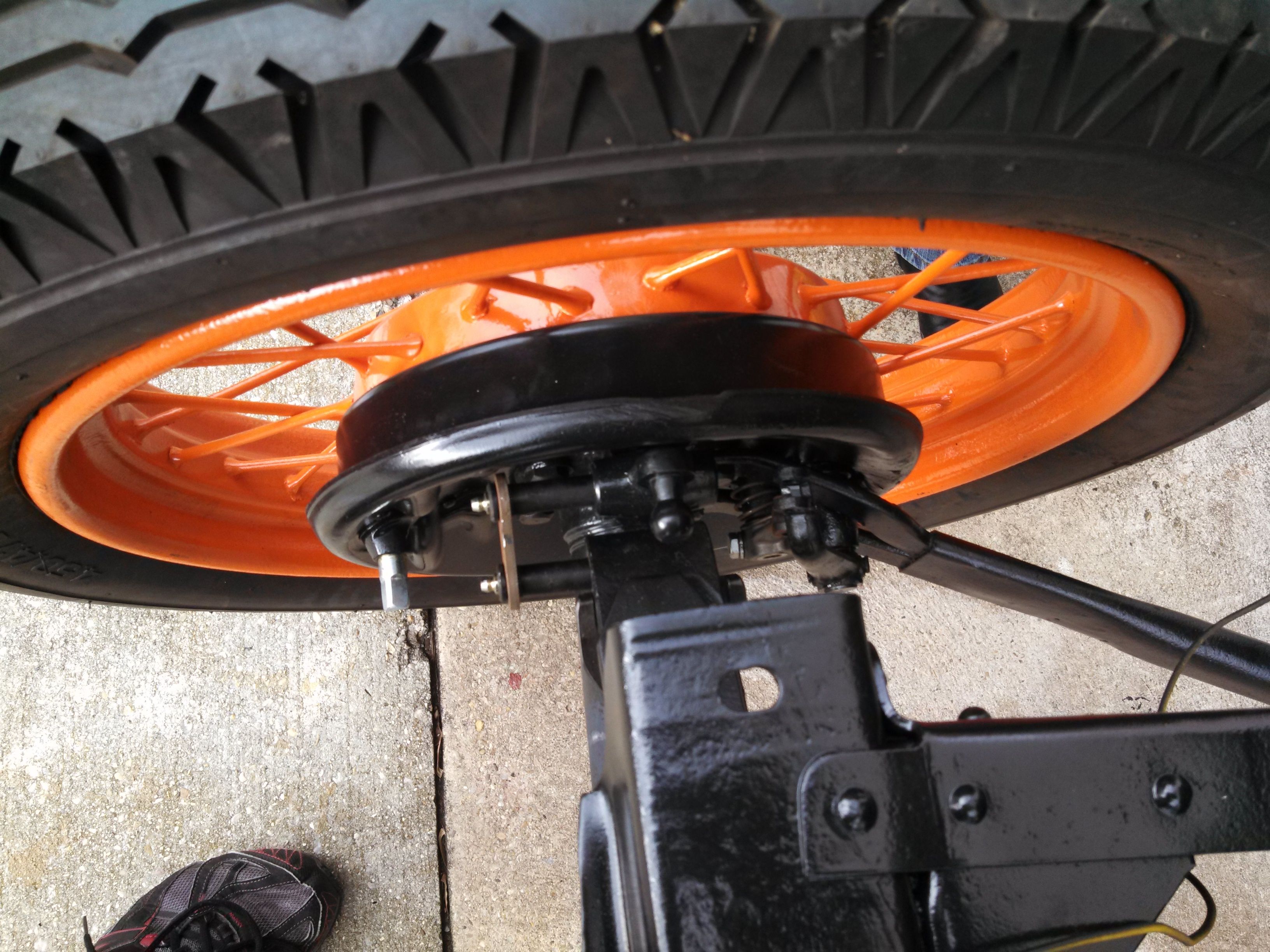
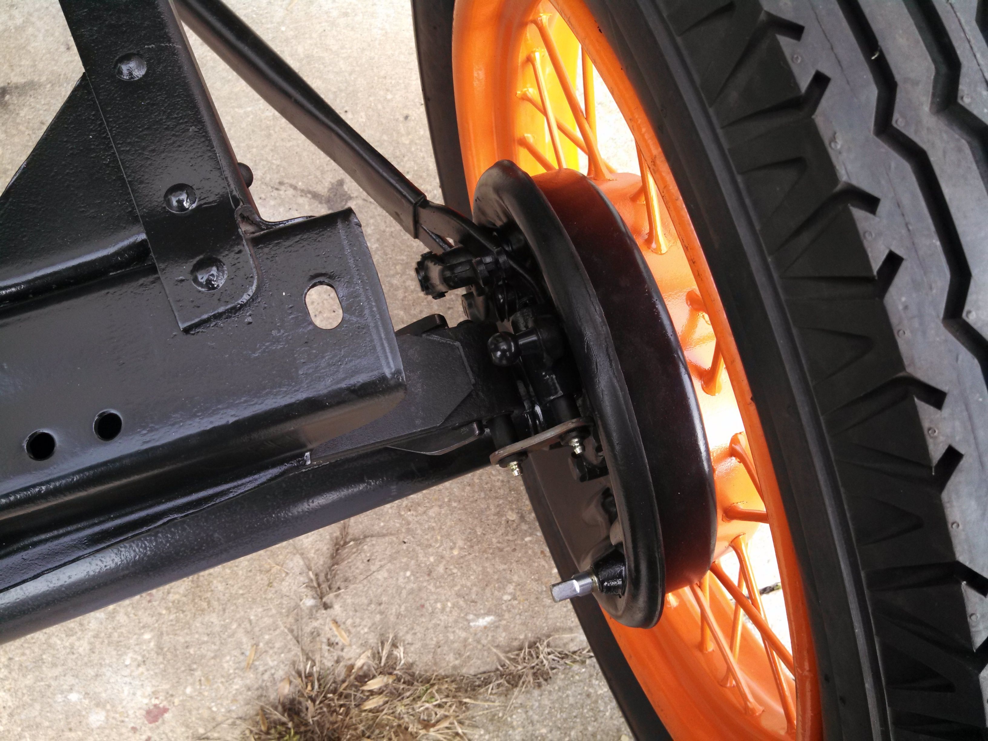
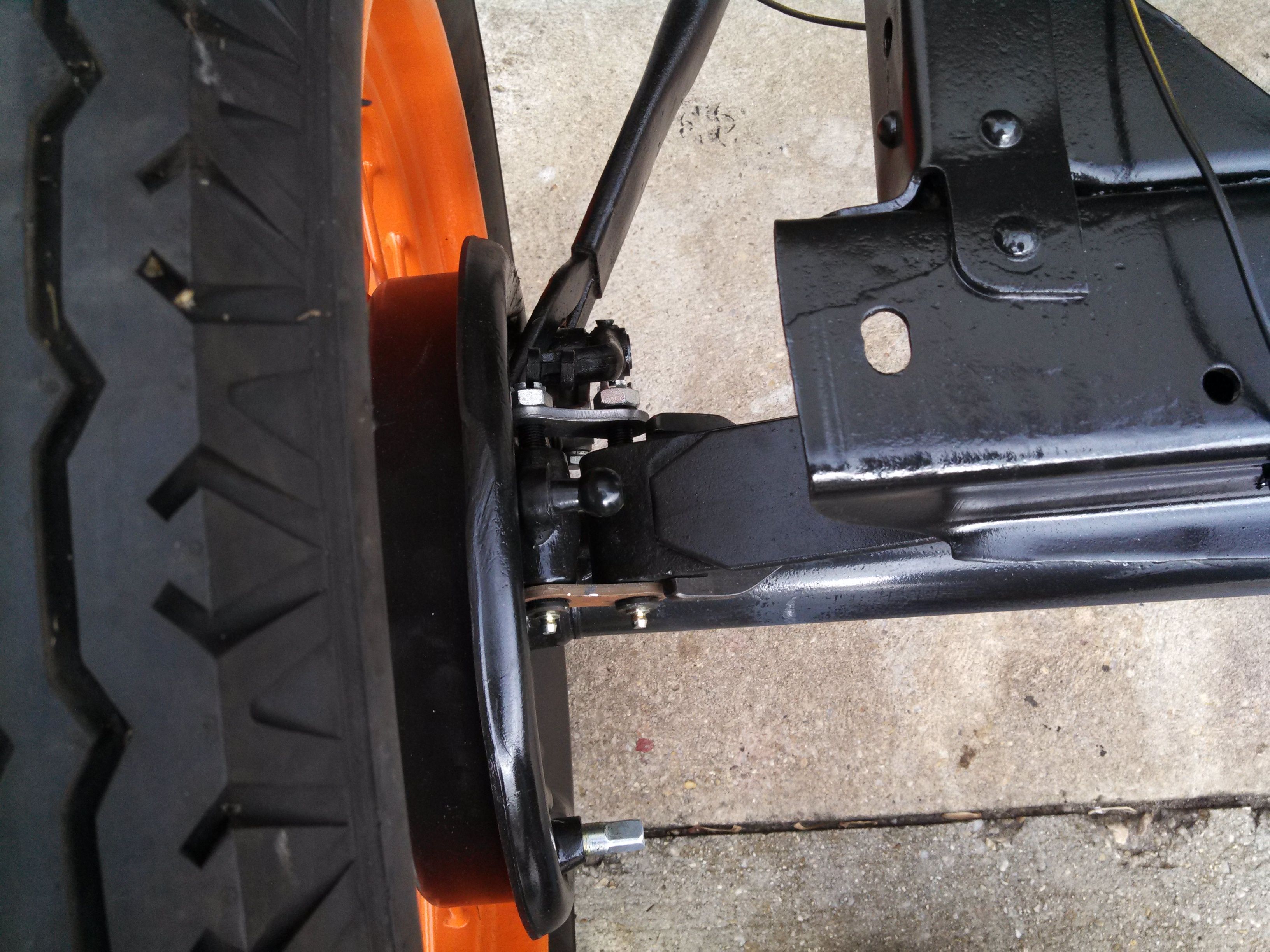
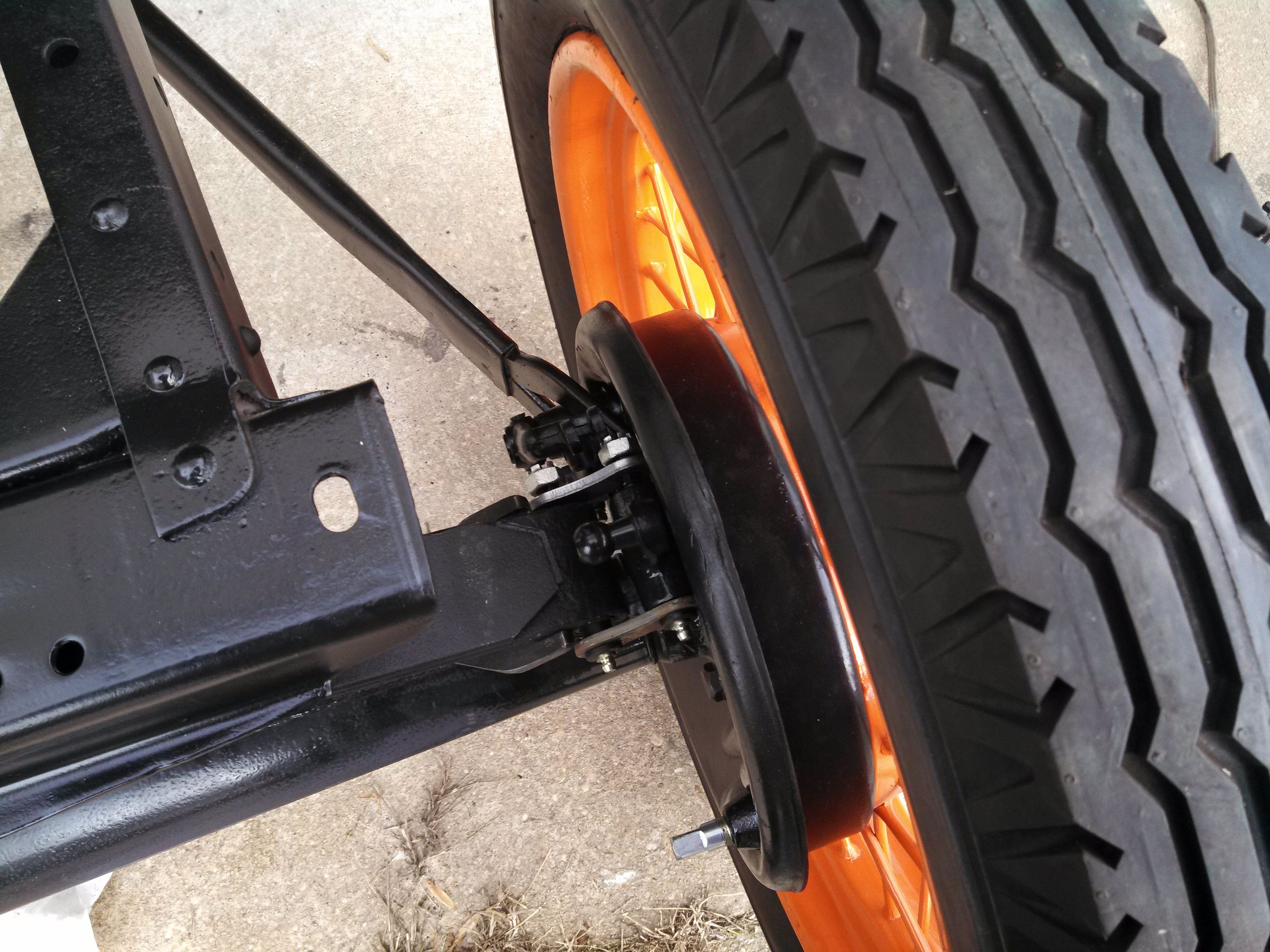
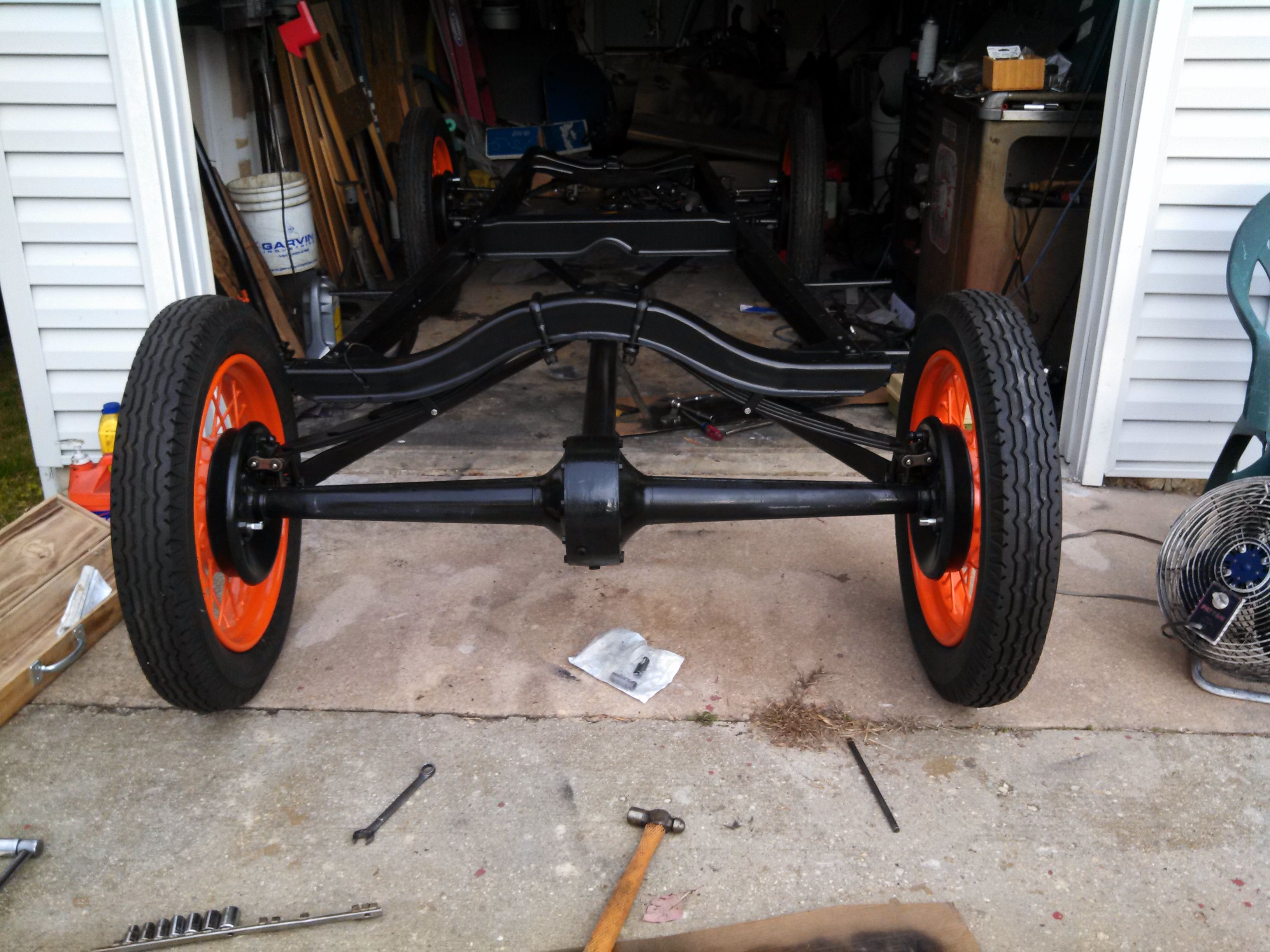
The first step was to get the rear end out from under the frame (where we had parked it last time). This could have been easier if that one brake wasn't hanging a bit, but the two of us managed to do it, although we scratched the axle up a bit in the process. Basically, I helped my daughter move the axle a bit, and then I picked up the frame while she worked it out further. It took a few attempts, and I was getting kind of sore by the time it was done.
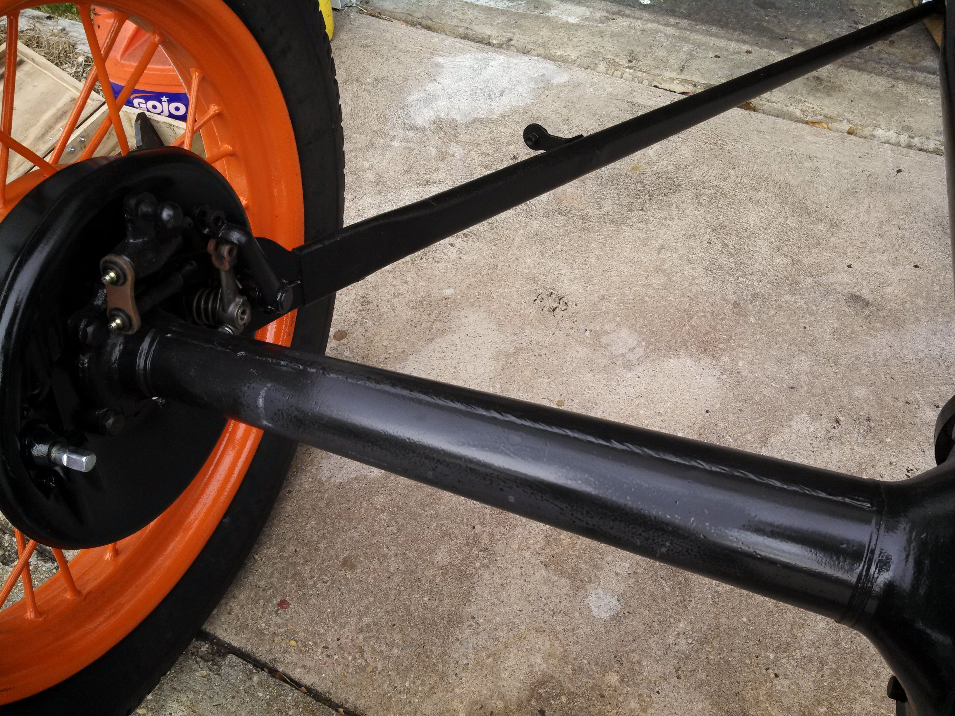
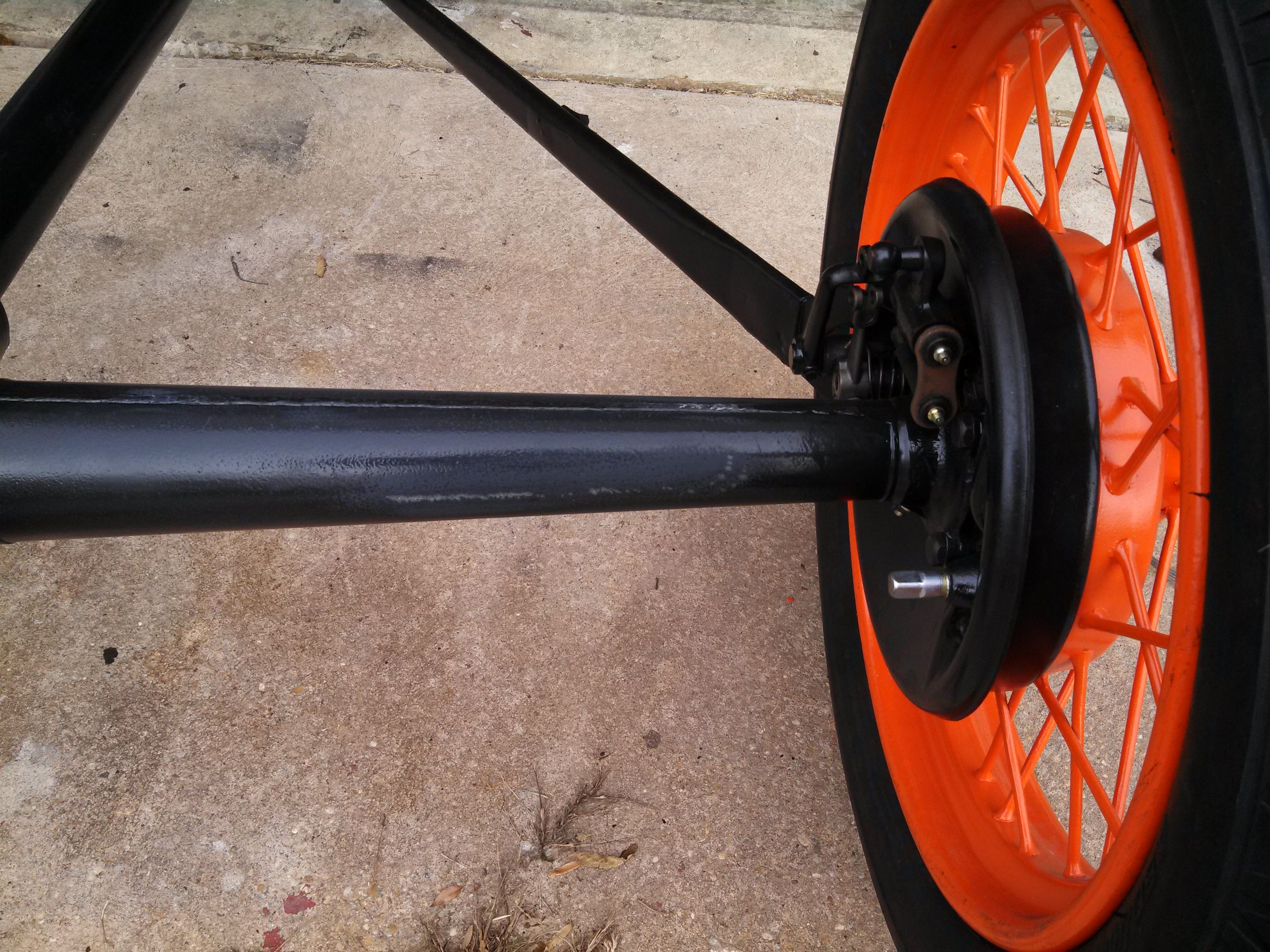
Once we got everything out of the way, we dropped the spreader into the springs and took some turns turning the nuts to get everything spread. You can see the process below, but the spreader had to go all the way out until it was just touching the springs before I could get the shackles installed.

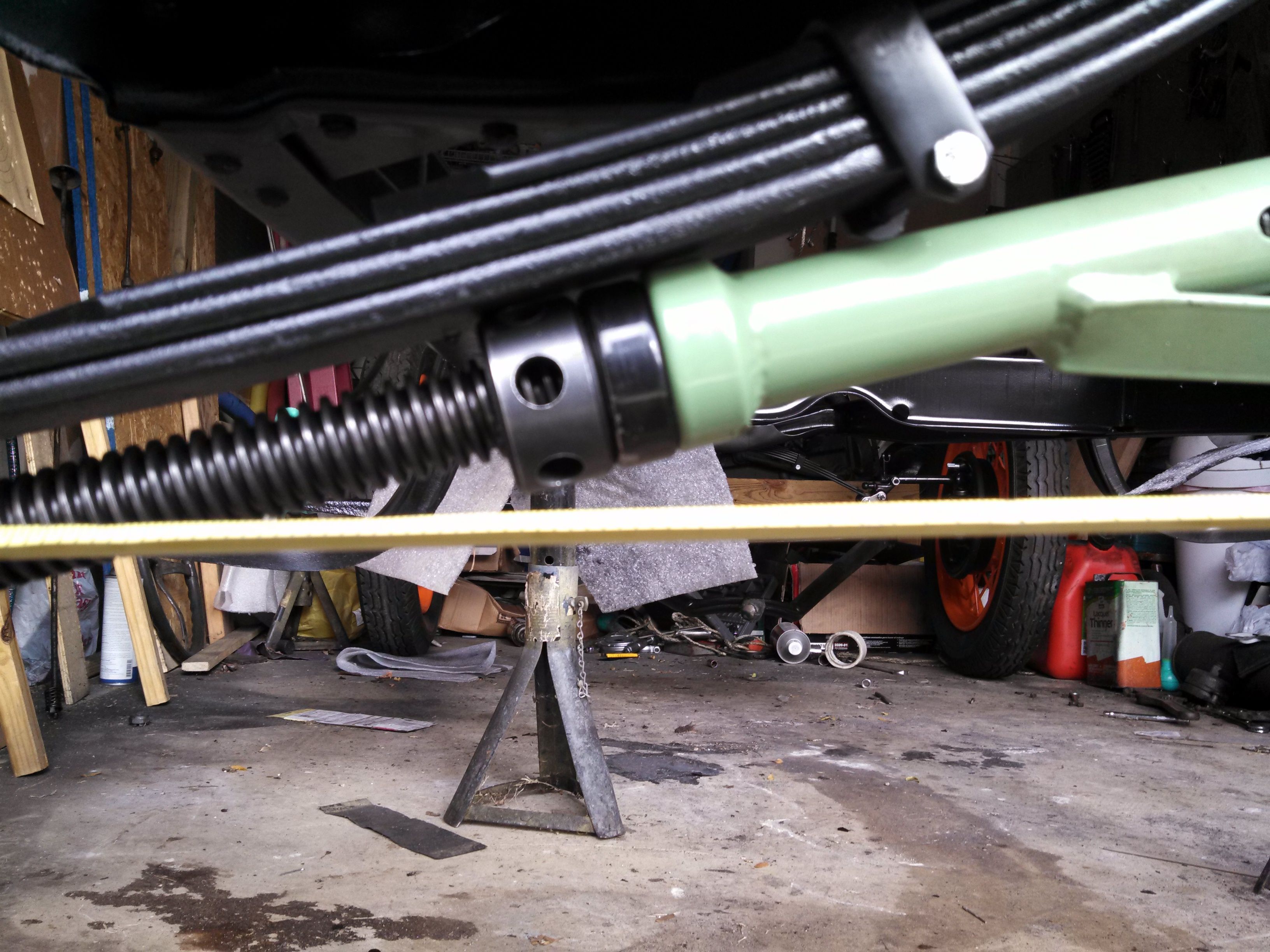
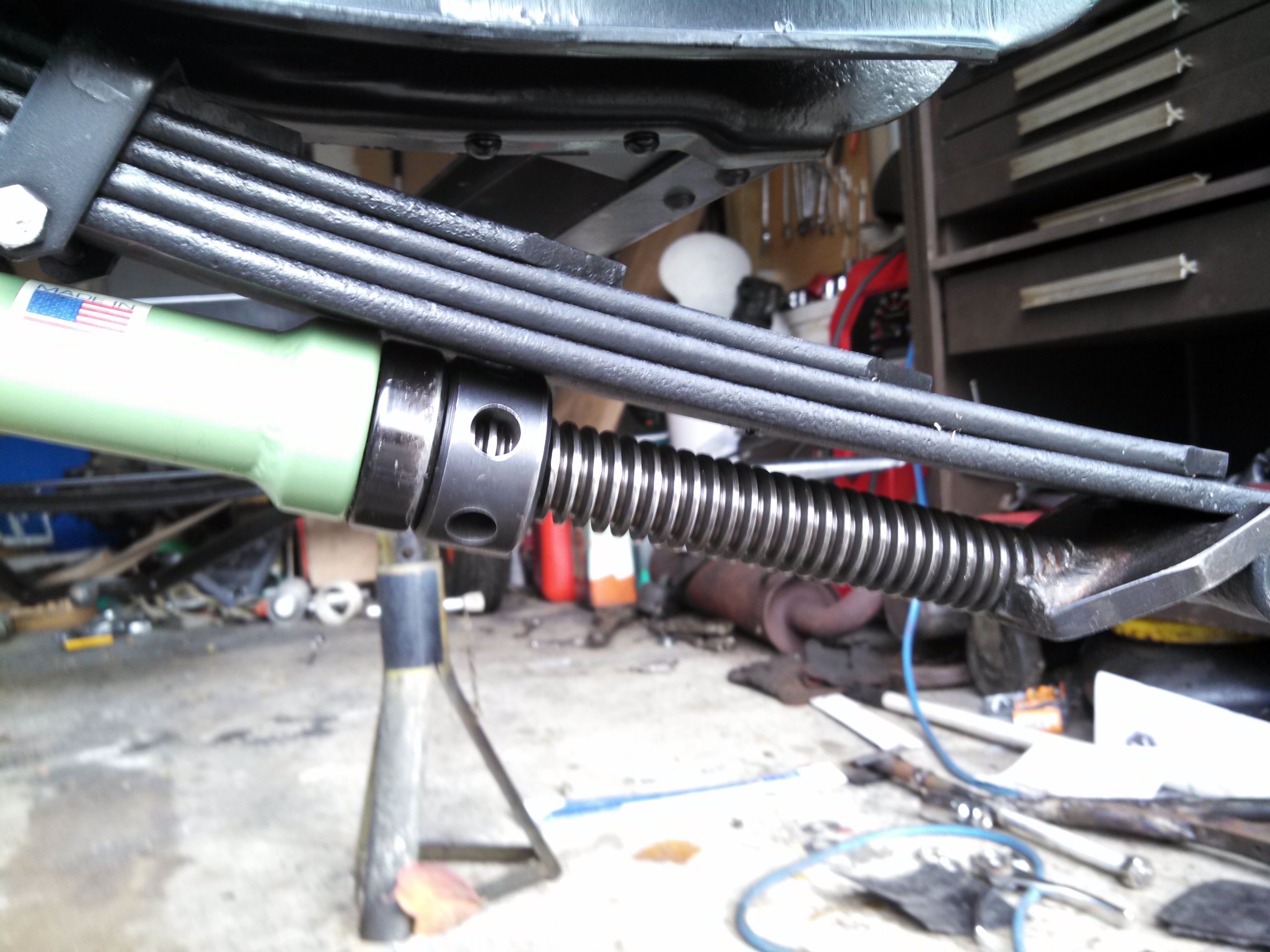
Once we had the spring spread, it was only slightly troublesome to get the frame and axle aligned so we could get the springs installed on the perches. I worked back and forth between the sides to try to ensure even application of pressure. A few light taps from a pall peen hammer helped out a lot...
Getting the cotter pins into the castle nuts was a little problematic, but not too big a deal. I'm thinking that this would all have been a lot easier if we had mounted the spring on the axle first, instead of mounting to the frame first. Just my $0.02, foe what it's worth... I also sanded down, and shot some primer over those scratches. Unfotunately, it was darned cold by the time I got to the primering bit, so I imagine I'll have to do it again...
Looking at the above picture, I can see it's going to be a real pain to install the shock absorbers, whenever I get around to it...
When we installed the spring up on the frame last time, I didn't torque the nuts down, or insert the cotter pins. This seemed like a good time to do it. I tried to evenly apply pressure to no more than 75 ft-lbs, and then gave small movements to find the pin hole. This worked great on the rearward set of nuts...
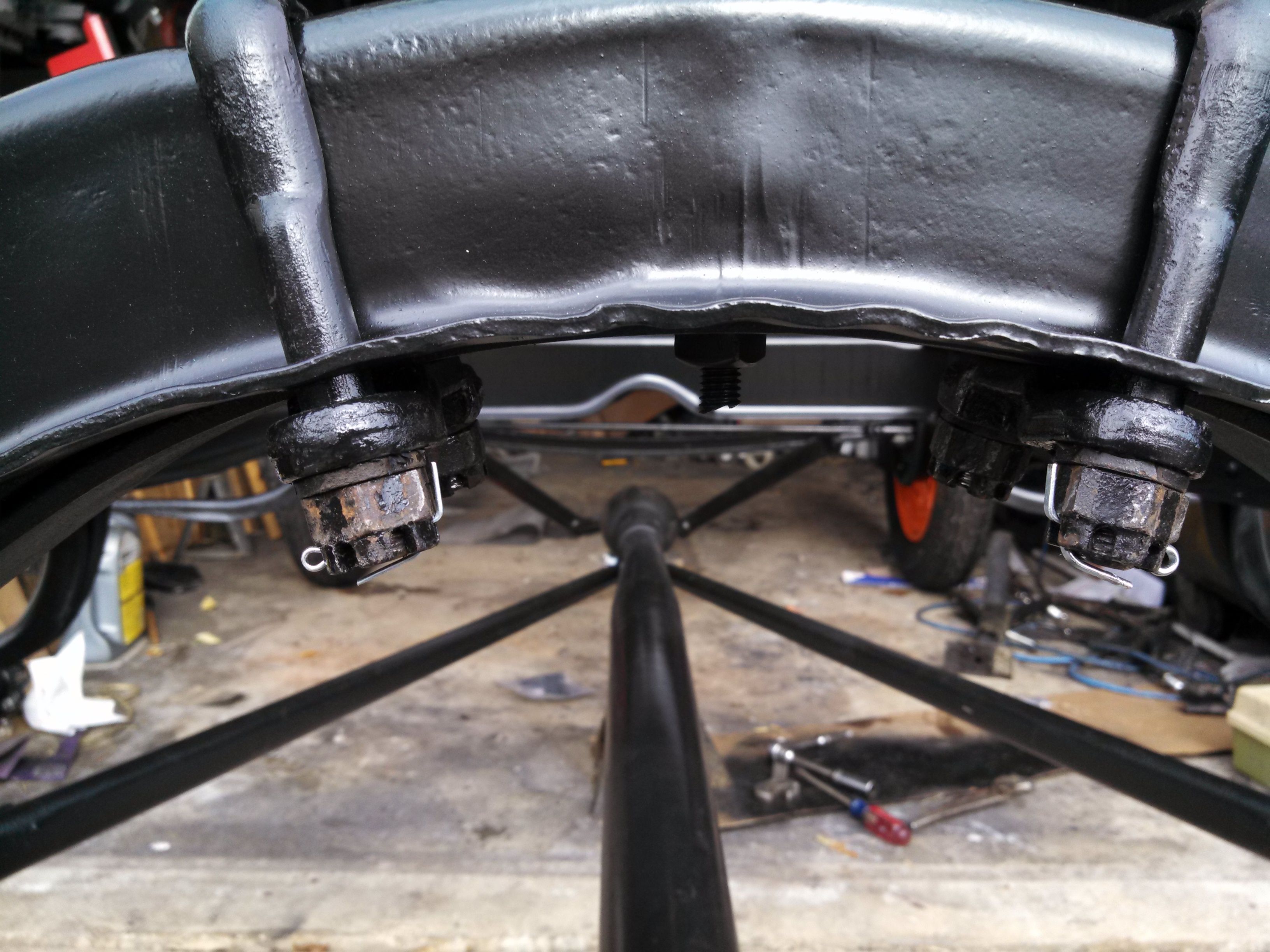
But then, when I tried to get the forward cotter pins installed, things fell apart. I was having a hard time finding the hole, and realized the nut needed to go about a quarter turn tighter on the U-bolt. As I tightened, there was a funny toink! sound. Not a snap, not a bang, but toink!... And then the nut started to slide off the bolt!
Now, I can maybe take some blame for over-torquing, but I'm pretty sure I didn't. I think I just saw a failure due to a combination of 80-year-old metal fatigue, and hydrogen embrittlement.
"Hydrogen embrittlement," you ask? Yep. Remember last month when I dropped those parts into a bucket of muriatic (hydrochloric) acid? Also known as HCl, it works because the polar water molecules strip the hydrogen atoms from the chlorine atoms, making a very ionic mixture. Notice the smell when you use it, a fair amount of the chlorine escapes into the air, and the hydrogen is free to do whatever it may - including leech into the metal. So, be forewarned. I'm not saying this is absolutely what happened, but I'm betting it's at least a part of it.
It was also interesting to see how the failure manifested - this is the first time I have ever seen a thread failure this way. I mean, I've over-torqued things, and broken bolts and stripped threads before. I've cross-threaded things and ruined them that way before, and that's what the bolt looks like - like it was cross-threaded. But the nuts look to be in really good shape, with no damage at all. Not only that, but I was able to turn them most of the way on by hand, so they were surely not cross-threaded. ennyhoo, here's a pic:
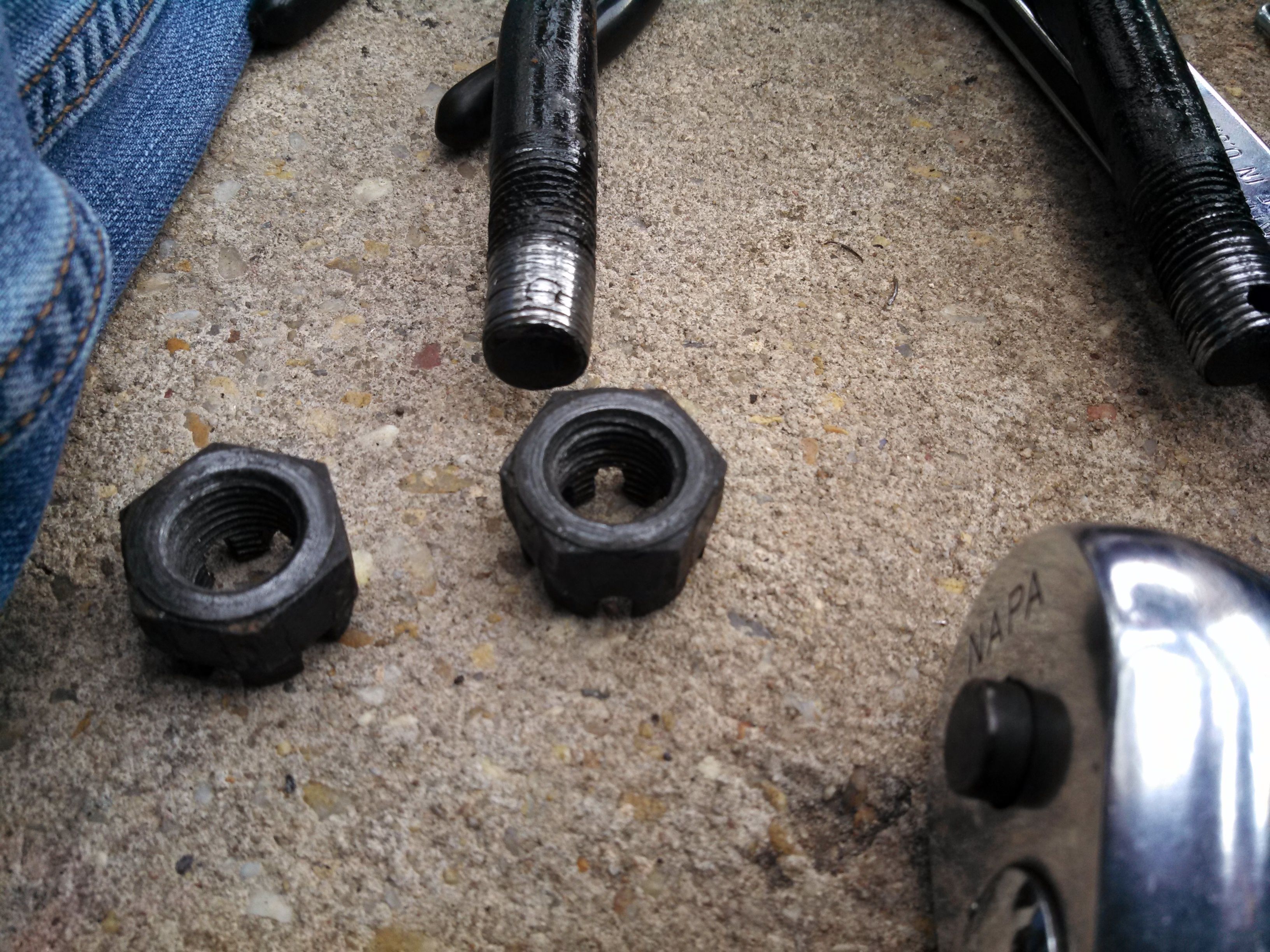
I went ahead and ordered some new nuts and bolts from Bratton's, but they gave me a call and told me they're out, and both of their suppliers are out, too. So, for now these are on back order. That's okay, there's plenty of things I can do between now and when they'll get hidden by other stuff. So now, I'm looking for a heater to keep the garage warm enough I can work in it over the winter. Any ideas?
Last modified on 12/03/13